Friday, 31 January 2020

Friends of the Baldwin Gas Mechanical


As we are on the subject of friends, we were sorry to learn of the deaths of Jim Wild and John Turner, great characters within the small world of 16mm. Derek Wiggins features a tribute to Jim in the e-magazine, Throwback Modeller (TBM) issue 13. I contributed a word or two as Jim and Colin Binnie, also sadly missed, had managed to rescue a locomotive, Hohenzollern 447, from utter obscurity. This tiny loco of German design had a conical boiler.
Do get TBM issues 13 and 14 if you can. As well as information about Jim Wild’s models, it features Colin Binnie’s unique General Arrangement of the Hz447, and the story behind this extraordinary military locomotive.
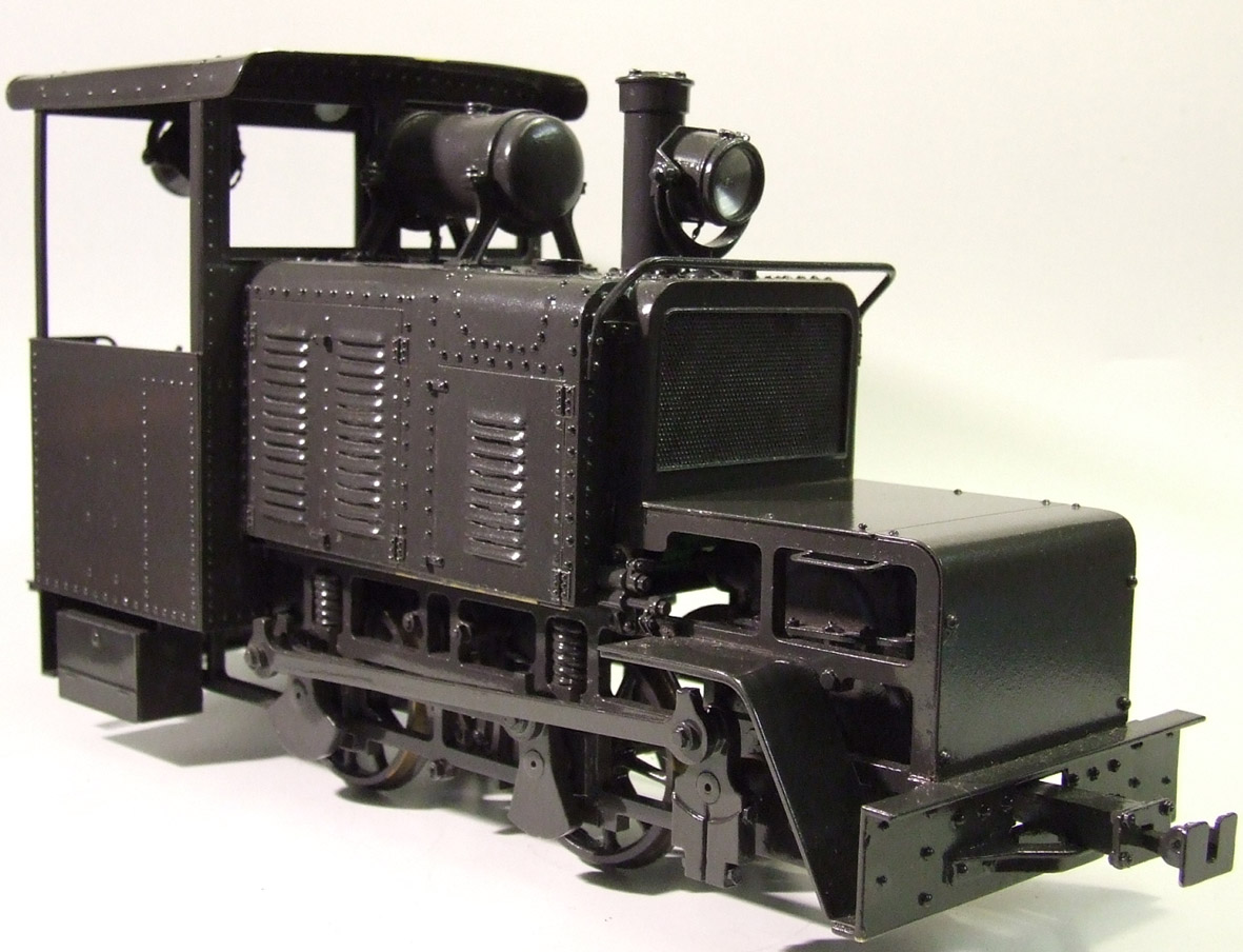
16mm scale  Baldwin Gas Mechanical, 50hp version, as used by both the French and the AEF 1916-18. Wrightscale model

The last blog explained a little of Malcolm’s fascination with another tiny giant of Military Narrow Gauge, the Baldwin Gas Mechanical locotractor. It would be good to provide a little context, by featuring two other petrol powered locomotives of the period. These were the Dick Kerr 40-45hp petrol electric tractor and the Simplex. Both were British made.
In theory, the Baldwin Gas Mechanical was developed later than both of these. 
The story of the Simplex goes right back to 1914. Although the BGM order date of 1917 is definitely after the time that the Dick Kerr was commissioned, November 1916, the story is a little more complicated. Certain aspects of the BGM date back, possibly, to the 19th century.
16mm model of the Pechot Bourdon 0-4-4-0,. The lines of the central chassis are angled in a way that is reminscent of the BGM. Model built by Henry Holdworth, photo courtesy J. Hawkesworth.
The mighty Baldwin Loco works of Philadelphia had been involved in the 14-18 War since 1915. Although the USA was not at the time a combatant, many of its businesses were arms suppliers. As the Central Powers were blockaded, most of the goods were purchased by the Allies. The French took a 19th century blueprint, the Péchot-Bourdon locomotive, to the USA. Among the first Baldwin locomotives to cross the Atlantic were these Péchot-Bourdon steam locomotives, no less than 280!
As mentioned earlier, it soon became clear that steam engines near the Front were a liability. For a start, they were far too visible to enemy artillery. Both the Germans and the Allies looked to the new Internal Combustion technology to provide smoke-free (well, relatively), spark free transport. This class of locomotive has been given various names but for convenience I’ll use the general term locotractors.
The role of the Russian Army is being reassessed; in 1916, they commissioned locotractors from Baldwin. Soon after, the French ordered 600. In my personal view, Baldwin drew both on the Péchot-Bourdon and the Russian designs for the glorious beast that is the Baldwin Gas Mechanical. The Russian locomotive is an obvious ancestor. Even an amateur can see how the coupling arrangement, large bonnet and louvred sides passed from one to the other.
Blueprint of the Pechot Bourdon chassis. It was carried by two steam bogies, each linked to the chassis by a revolutionary flexible joint and steam lines. Courtesy of the CAA, Chatellereult
It can be argued that, to reassure the French, the Baldwin works offered something that was also reminiscent of the Péchot-Bourdon. The nature of the design required a very strong chassis frame. It was supported by twin independent, sprung steam bogies. It in turn had to support the firebox and boiler arrangement while also transmitting the tractive effort of the locomotive to the train. This thinking, I feel, helped to give the Baldwin Gas Mechanical its wonderful and distinctive frames.
16mm models of a Baldwin Gas Mechanical and three forms of the Simplex. BGM by Wrightscale, Simplex models by David Smith as is the front of a Dick Kerr, just visible at left. Photo J. Hawkesworth.
Meanwhile, the British War Department were approaching the petrol locomotive from a different viewpoint. The Simplex design goes back to 1914 when the Motor Rail and Tramcar Co of Bedford offeredthe design to General Kitchener. At that time it was refused. In 1916, British High Command finally caught up with the folk on the ground and placed an order.
The main advantage of the Simplex was simplicity – the clue was in the name. The original had a channel-steel underframe and overall length was just under 9’. A 20 hp petrol engine was mounted in the middle, powering a three-speed gearbox which could run equally well in forward and reverse. Chain drives powered both axles. The driver faced sideways at the end opposite the radiator – good visibility in both directions.
The 40hp Simplex followed. The design was distinctive. The underframe was now sheet steel rather than channel, overall length was just under 12’ the driver sat in the middle rather than at one end, the ends of the frame were ballasted to improve track adhesion, the motor was more powerful and there was armour.
A 20 hp Simplex (David Smith) hauls a Pechot artillery wagon (Wrightscale) while an armoured Simplex looks on. The radiator is at one end while the driver sits sideways at the other.
This varied in degree. In the Open type, the flammable engine parts were covered with sheet metal and the driver had a canopy to keep off the worst of the weather. The Protected tractor had all this plus steel doors to the driver’s cab. The Armoured design was almost completely enclosed in sheet metal. Its beetle shape has evoked much fondness.
In number and in ‘character’, various versions of the Simplex almost rivalled the Baldwin locotractor.  A total of 590 in the four designs were supplied to the Front. It is possible that the famous confusion that hovered over the Baldwin Gas Mechanical may have been caused by the Simplex which was supplied as 20hp and 40hp. The BGM was supplied as 50 hp to the French and, slightly later, in 35 and 50hp forms to the American Expeditionary Force. A number of early histories assigned to BGMs the horse-powers 20 and 40. Could the cheeky little Simplex have caused the confusion? 
The Dick Kerr petrol-electric was another British answer to the BGM. The BGM was 23’ long, the Dick Kerr around 15’ At roughly 7 tonnes, the two designs were comparable in mass. Power was 40 hp compared to 50. Loco drivers had similar complaints about both – their agonising slowness. Both were also top heavy. Although the model does not show them, the Dick Kerr prototypes were equipped with massive re-railing bars – no doubt for good reason. The Dick Kerr had distinctive louvred side panels, just like the BGM.
16mm model of the Dick Kerr petrol tractor, built by David Smith, showing the characteristic louvred panels. Electric pick-ups can be seen on the bonnet top. someone has nicked the rerailing bar! Photo courtesy J. Hawkesworth
But the two were the products of parallel evolution. The BGM was the product of US ingenuity applied to French engineering. Only the British could have come up with the Dick Kerr. When the War Department Light Railways Programme B was put forward in the autumn of 1916, electric locomotives with overhead pickups were suggested. They would not generate steam and sparks and thus would stay out of sight of enemy artillery. The electric pick-ups proved to be an issue! Although the plan was quickly abandoned, the design specified electric pickups on locomotives. Effectively, electric power was generated from by a petrol engine; when stationary, the loco had a second use as a generator. Wherever there was aworkshop, a Dick Kerr or its sister, the Westinghouse, would be in attendance.
The specifications were put out to two companies, British Westinghouse Ltd and, slightly later, Dick Kerr Ltd. Both produced 50 pairs of locomotives. Though both designs featured detachable armour-plating, contemporary photos suggest that Dick Kerr Ltd put more thought into protecting the cab. This fact, and the delicious louvred panels have made the Dick Kerr the favourite between the two designs.
16mm Dick Kerr (David Smith) and BGM (Wrightscale). They are comparable in dimensions and power. Photo courtesy Jim Hawkesworth
There are some lovely proprietory 16mm models of both the armoured Simplex and the Dick Kerr. David Smith has done much in this field. The late Henry Holdsworth painted and weathered the models in these pohotos, to superb effect. All three of these characterful locomotives have a place on a layout, whether in war-time or post-war guise. 

Tuesday, 31 December 2019

16mm scale Baldwin Gas Mechanical


We missed a deadline and our regular advertisement didn’t appear in the latest ‘Sixteen Millimetre Today’ magazine. You will want to know what you missed. This was the 16mm model of a Baldwin Gas Mechanical locomotiv. We have taken a fascinating prototype and created a model to run on 32mm track.
16mm scale Baldwin Gas Mechanical locotractor that we meant to advertise in winter 2019. Created by Wrightscale
The originals were developed to run on the 60cm gauge railways that supplied the trenches of World War One. We have long had an interest in this vast but forgotten network – more below.
We produced these models about ten years ago, using the best suppliers we could find. Unfortunately, these companies kept closing; and as small suppliers came up for retirement, they too just closed their garage doors. It has required a lot of time and energy in finding new suppliers of the right calibre .
One of our best was Adrian Swain. We were relieved when Sarah Smith of Sarum Models was able to take over as a high quality and efficient supplier.
The steel laser-cut frames were even more of a head-ache. Our first supplier did pass us on to another company but this in turn quietly shut its doors and threw away its working tools. Well! When we did find another company, Malcolm had to redraw the frames and present them in a form that their laser computers could digest. This all had to be fitted in while we earned a living and kept up with family matters.
Here’s what we were going to say in the advertisement.
‘A batch of these interesting locomotives is going to be built or delivery early next year’ If you might like to buy one, let us know your name.’
Unfortunately, we cannot yet commit to a price because our suppliers in their turn cannot yet commit. They all quote a certain event which we keep being told will happen, but which doesn’t. This event hovers like a malign flying elephant, spreading uncertainty throughout the raft of small businesses on which we float. Thus, we will take your name without obligation, and give you an opportunity to buy once you know the price.
That is the substance of the advertisement.

THis part-assembled Wrightscale Baldwin Gas Mechanical shows the chassis frames, a standard Baldwin manufacturing feature. Photo and model MD Wright
We’d also like to share with you our delight in the model.
The prototype popped up in 1917, half-way through the Great War. In the early months, both the Allies and Central Powers realised a sad truth about the War. It was not going to be a war of movement, over quickly once one side had taken over the territory of the other. The French were not overwhelmed by the Schlieffen Plan and the Germans had a secret supply of ammonia for their ammunition. One side and then the other dug in along eastern France and the French Belgian border. Temporary trenches became permanent and the Western Front appeared.
Both sides were faced with a problem that few, at least on the Allied side, had anticipated – how to feed, water and quarter millions of soldiers and their artillery. The French, thanks to almost heroic efforts by an officer in their Artillery, Prosper Péchot, had a 19th century railway system which could be adapted. The Germans, always on the alert for good ideas, copied this promising system in the 1890s.
Colonel Péchot in 1907. Photograph courtesy of Raymond PECHOT
This wonder-working system depended on 60cm (roughly 2’)  gauge prefabricated track which could be quickly laid, or relaid wherever supply trains were required. Thanks to clever design using sound engineering principles, these miniature railways could support heavy trains, pulled by powerful locomotives. The horses, mules and humans who would otherwise have had to transport millions, yes millions, of tonnes of supplies in thoroughly inhumane conditions were spared. War Horse could eat his oats in (relatively) safe conditions.
The system was rapidly adapted. Temporary track gave way to proper permanent way. Importantly, a substitute was found for steam locomotives. By day, these sent up a plume of smoke, by night, a shower of sparks, an absolute gift for opposition artillery. By 1917, a number of designs of internal combustion engines had reached the tracks. Among the range of models put forward were rail-mounted cars. Outstanding among the Allied designs were the Baldwin locotractors. On the German side, Benzolloks (running on petrol) and Dieselloks appeared
For a number of reasons, the Baldwin Gas Mechanical locotractor built by the Baldwin Works of Philadelphia has inspired the greatest affection.
On account of the numbers built, it was sighted everywhere. When the USA entered the War in 1917, their AEF ordered 109 BGMs and 61 of the 35 hp version. Nineteen (or so) never crossed the Atlantic. An even larger number were made for the French – between 535 and 600, depending on the authority. If you want to know more about the numbering, Rich Dunn gives a good account in his ‘Narrow Gauge to No Man’s Land’ pp 98 to 109. Another excellent account is given in Dr Christian Cénac’s ‘Soixante centimetres pour ravitailler les fronts de la guerre de 14-18’
Partly built Wrightscale 16mm scale Baldwin Gas Mechanical
The BGM was seen in a number of settings – training camps, forestry railways, maintenance, shunting and, most importantly of all, taking supplies forward to the Front. The locotractors had the priceless advantage of being less visible than steam engines. They could run all day and night, as long as they were regularly refuelled. They were much easier to stop and start than a steam engine. As the driver sat side-on, reverse was no more difficult than going forward.  Imagine how this must have improved the lot of a squaddy under fire!
The BGM was truly international. We believe that the French/AEF design originated with an earlier locotractor made for the Russian Government. This was in 76cm (roughly 2’6”) gauge – the eastern front also had light railways though never to the extent of the west.
The BGM had character – so much locomotive perched on so small a wheelbase – the vast yet reassuring ‘face’ - the fascinating louvred sides and the frames, the frames, the frames. It was not so much a chunk of metal, but an embodiment of the spirit of US manufacture. The Baldwin Works combined the rugged individualism with the new techniques of the assembly line.
A Baldwin Works Assembly hall pictured in 1915 showing how rugged individualism could be happily combined with the techniques of the assembly line. Photo courtesy Raymond PECHOT
On the one hand, Baldwin could not have achieved its vast productivity without a system. Each product was built in a huge hangar where a team could perform an operation then move on to perform the same on the next. Yet at the same time, these teams could improvise where needed. If the factory drawing didn’t quite work, the foreman could devise a work-round and trust the team to deliver. The BGM design shows the best of US flair of the period.
An enticing air of mystery still hangs about the BGM. Historians continue to argue about the numbering and hoiw to track down missing examples.  When the US government placed the order with the Baldwin Locomotive Company, they may well have stipulated 20 and 40 horsepower. What they got were 35 and 50. This may have been because the more powerful gasoline engines were more readily available. Certainly, the greater power was more useful under battlefield conditions – more likely to achieve the theoretical speeds of 6.4 kph (4 mph) and 12.8 kph (8 mph) in top gear.
They had disadvantages, the main one being that their power output could be less than a third of a steam loco. It didn’t always achieve the quoted top speed. Soon the people in the field did what they always do - demand more power.
Though track adhesion was quite good – four driving wheels took 100% of the loco’s weight – the corollary of the neat wheelbase was a large overhang front and rear.  It tended to jump off the track. Furthermore, as the design was pushing the envelope of contemporary design, the gearbox and clutch were unreliable. There was another, disadvantage, plain as the nose on its face. The gas/petrol/essence was carried in a tank on top of the bonnet. When it had just been refuelled, this raised the centre of gravity. When it was nearly empty of liquid, the cylinder remained full of hydro-carbon gas, highly vulnerable to stray ordinance.
Some unpatriotic servicemen were photographed driving the British Simplex and the French Schneider 0-6-0 petrol loco.
A lovely example of the 50hp BGM is preserved at Froissy, Somme
The Baldwin locotractor has had a long afterlife, partly because it was, in its own terms, an excellent loco and partly because prototypes were plentiful. Long after the First World War, they were used in military camps in the USA – Camp Humphreys East Virginia, the Proving Grounds at Aberdeen Maryland, Fort Benning etc. Many were sold as War surplus.  Moelwyn on the Festiniog Railway is a heavily disguised Baldwin locotractor. Lovely examples are also preserved in France.
These prototypes keep interest alive; we have had encouraging interest in the model
The Wrightscale model for comparison

Saturday, 23 November 2019

Wrightscale and military railways


The Péchot Story and Epinal
We are delighted to see that Epinal has rediscovered its military heritage! One site, the Fortiff'Séré - Le site web & l'association Séré de Rivières run by Cédric and Julie Vaubourg has ample photographs showing how the system is being restored.
A Séré de Rivières fort, lovingly restored. A 60cm railway runs over the defensive ditch in through the gate. THis is Uxegney near Toul which was quicker to preserve its heritage. Photo Malcolm Wright
As enthusiasts of the heritage of Péchot military railways, we visited Epinal in the early Oughties. In those days, it seemed unaware of its interesting heritage. So here is some background.
Epinal is the county town (chef lieu de département) of Vosges in eastern France. As such, for many years it was considered vulnerable to invaders from across the nearby Rhine.It was therefore a centre for fortifications, gradually increasing in complexity. A castle dominates the centre of town.
After the Franco-Prussian War 1870-1 and the loss of the department of Haut Rhin to the east, Epinal became a frontier town. In 1874, smarting from their defeat, the French government authorised General Séré de Rivières to plan a line of defences. These stretched from the Channel to the Mediterranean; there were also naval forts defending the Atlantic approaches.
Epinal found itself a centre for these new fortifications, planned, built and commissioned between 1874 and 1882.
These new forts, several per city, were huge (a typical outer face was 100 metres long) and earth-sheltered. Each was surrounded by a ditch; the spoil from the ditch was used to construct a glacis (vast sloping outer wall) as further protection. Although many forts were rectangular, where conditions dictated, they could be other four-sided or five sided shapes, thus the name polygone.   At the height of building the project absorbed up to one-tenth of the entire national budget.
What high explosive could do to a fort, in this case Maubeuge. Photo from Illustration magazine courtesy MD Wright
It was a huge undertaking but almost as soon as the forts were built, they were out of date. Melinite, a precursor of TNT, was introduced. In 1886, the government experimentally bombarded the fort of Malmaison with the new high explosive shells. The Press got wind of the experiment and turned out to watch.
The beautiful, if slightly old-fashioned, fort was reduced to rubble in an afternoon. If the fort had been defended all the occupants would have died, if not from a direct hit, from building collapse. The Press weren’t going to keep quiet about this threat to Our Boys. Séré de Rivières and the Committee for Fortifications were ordered to sort out the problem. Urgently.
They came up with a plan. The forts would be safe as long as the opposition couldn’t get within range. This meant that each fort had to be surrounded with mini-forts. As guns became more sophisticated, the mini-forts had to be surrounded with micro-forts and these in turn with buried guns batteries. The central fort was buried, with  a retractable gun turret and the ammunition was stored deep underground. The principle was sound. During the First World War, it took the Germans nearly a fortnight to subdue a Belgian fort which had no ring of defence. The Verdun system, which was well-defended, held out during the long and savage Battle of Verdun.
But … There were a few ‘buts.’  The first problem was cost. The Treasury could not pay to build a defensive screen all the way down France. They decided to concentrate on the border with Germany – Belgium, Britain and Italy seemed less of a threat. This was to prove a mistake. Frontier defences would be concentrated on four centres – Verdun, Epinal, Toul-Nancy and Belfort near the Swiss border. Thus Epinal which had a ring of sixteen forts had these protected by thirty for redoutes and these in turn by sixty four gun batteries.
Prosper Péchot photographed in 1907, courtesy Raymond PECHOT
Solving this problem generated a new one. To ensure that all these defences had the latest in guns and ammunition, they needed more than footpaths and a few mules. Fortunately, a solution was at hand - developed for the French Army by one of their own.
Prosper Péchot, an officer in the Artillery, had developed an ingenious portable railway in 60cm gauge. In ‘Colonel Péchot: Tracks to the trenches,’ Sarah Wright has described how he took ideas from the Decauville Company, the slate quarries of Wales, the Darjeeling Himalaya Railway and developments in North America to create a system of portable railways. Small locomotives could run on light track without disturbing the substrate – well, not very much. Enormous loads could be carried on rolling stock as long as such loads were carried on enough axles. Best of all, the trains could cope with track laid on hilly ground.
He, unfortunately, had rivals. The French Génie (Sappers) preferred metre gauge as this was proven technology. The ground around all these forts was hilly. Verdun had the Woevre, Toul the Argonne (politely known as the Parc National de Lorraine), Belfort the Alps and Epinal the Vosges. The French Army decided to spend a year testing both.
Bois l'Abbe was a minor fort in the system protecting Toul. Enthusiasts have recently relaid the 60cm railway which used to connect it to other forts. Photo MD Wright.
 60 cm was tested  between Toul and Fort Lucey, perched on a hill.  Metre gauge was to be tested above Epinal. It was planned to create a system between the forts of Girancourt and Thiéha. By spring 1888, Toul and Lucey were linked. They were nowhere near building a metre gauge line. The Génie hoped they could cover up the problem; when the tour of inspection arrived, they were treated to a slap-up dinner in town. When the inspectors arrived at Toul, they were given a picnic on the glacis at Lucey, having travelled up on a functioning 60cm railway.
The workhorse of the 60cm system was this sturdy, well-sprung wagon capable of taking ten tonnes of supplies along light track. 16mm Wrightscale model
Justice was served. 60cm was proclaimed victor.
This ingenious 60cm gauge rail-mounted crane could handle heavy ammunition safely . 16mm Wrightscale model
Other problems were not immediately solved. Hygiene was one. Human beings produce wet and dry manure. If the castle is a lofty construction, high above the heads of attackers, such products are welcome additional ammunition. Visitors to a typical medieval castle can admire the garderobes, handily placed over of the opposition! When the fortification is underground, waste not so welcome. It would trickle into the living-quarters, ammunition and water supplies. Nineteenth century France found n adequate solution.
Revolving gun turret, cosily earth-sheltered. Unfortunately, it was not well ventilated. Photographed at Villey-le-sec (near Toul) by MD Wright
Another question was ventilation, a perennial problem for underground work-places. An elaborate system of passive-stack ventilation ensured a brisk enough air turnaround for normal life. When we visited an underground dormitory, the air smelled fresh. Unfortunately, this was not adequate for heavy work underground with all the nitrogen compounds produced by high explosives. A few minutes in these conditions produced nausea and headaches. Prolonged exposure was dangerous to health.
For these reasons, forts rapidly became intolerable under siege conditions. Epinal was never truly tested. During World War One, Verdun suffered a ferocious attack; even when it was clear that the Germans were preparing their assault in March 1916, Forts Vaux and Douaumont were not properly defended. Only when Pétain introduced troop rotation was it possible to maintain a garrison in the remaining system.
Gate to fort Girancourt, near Epinal. Until recently, this was being allowed to return to Nature. Photo by MD Wright
After 1918, the frontier was pushed eastwards and the Séré de Rivières defences were made redundant. The system in the Toul-Nancy area was used until 1940 for training. When the Second World War was imminent, other forts were given some attention. The classic ‘umbrellas’ – a post supporting strands of barbed wire - as used around the Maginot line - were installed around many old Séré forts. They were still in evidence around Girancourt in 2004, concealed in vegetation.
Until the late 20th century, many fort were still used by the Army. These were then released into the care of enthusiasts, and a number of forts were rescued. Typical would be the ‘La Citadelle’ Association of Villey-le-Sec near Toul which had a 60cm working tourist railway by 2007.  Uxegney, Lucey (both Toul), Batterie de l’Eperon (above Nancy) also had enthusiasts’ groups.
Around Epinal, forts such as Girancourt and Thiéha submerged into the forest. In the years after the War, they had been returned to the local commune who saw in the concealed ditches, barbed wire etc nothing but hazards so they were fenced off and the public kept out. Fortunately they are now, as of 2019, being rescued. The Fortiff’Séré website/facebook gives details; we were particularly gratified to see Girancourt and Thiéha emerging from the trees and brambles. 
Gate to fort Thiéha near Epinal, also being retirned to Nature. Photo MD Wright
As well as 'Colonel Péchot: Tracks To The Trenches', see if you can find a copy of 'Chemins de fer militaries a voie de 60' by Wahl and Metz.

Wednesday, 13 November 2019

16mm: the wonder of small


Friends of Wrightscale may wonder how Malcolm came to make his locomotives. He didn’t choose them. They chose him.
The Bagnall Excelsior, the Kerr Stuart Wren and the Quarry Hunslets of North Wales all inspire great love. 16mm model of Excelsior in its 0-4-0 configuration by Wrightscale
Enduring favourites have included the Bagnall ‘Excelsior’, the Kerr Stuart Wren and Quarry Hunslets especially the ‘Alice’ class. Their main characteristics were: 2’ (60cm) gauge, small mass, carrying their own water tank and (usually) 0-4-0 configuration. Their charm even involves contradiction and paradox.
Here are a few thoughts about the appeal of each.
Wrightscale 16mm Wren

The first model in 16mm gauge was the 0-4-0 Wren. In 1980, we met a prototype, Pixie, at Leighton Buzzard, pulling a passenger train and Malcolm was immediately hooked. He then saw a model Wren,  as a 5 inch gauge live steamer and he thought ‘If it can be done in 5 inch, how about doing it in 32mm gauge?’ At the time, the craft of 16mm scale was the preserve of a few enthusiasts and I’m pretty sure that Malcolm was among the first to think of fitting up a locomotive to run on live steam.
16mm Wrightscale Wren
If you can look back on learning - undoing mistakes and the triumph of success, repeated over and over - with any pleasure, then Malcolm looks back on the Wren with great fondness. When he unveiled a working prototype, there was general admiration. Of course there are now many beautiful steam locomotives which run on 32mm track, but this was one of the first reasonably faithful models of a recognisable prototype.  
The Wren has always attracted admirers.  The prototype was the smallest locomotive built by Kerr Stuart but the company’s most successful product. 163 were built between 1904 and 1929 when Kerr, Stuart folded into the Hunslet Engine Co of Leeds. The marque lives on - it was transferred to Statfold Barn. A couple have been recently built, but for preserved railways.
The 20th century Wren prototypes were usually purchased for construction sites. The nature of such railways was ephemeral and the locos were put to work hauling skips of rubbish. The Wren's many admirers may even love it because because of the unglamorous nature of its working environment!. As mentioned above, models have been built in various scales. About 160 Wrightscale 16mm Wrens have been  created over the years, comparable to the number of prototypes.

Wrightscale Alice class Quarry Hunslet locomotive 16mm scale
We had seen a Quarry Hunslet five years previously when we visited the Festiniog Railway but at that time, Malcolm never thought of turning it into a live steam model. When 16mm scale took off, Tony Sant was the first into live steam Quarry Hunslets. He and Malcolm agreed that with so much demand and so many variants of the basic design, there was room for more than one builder. Thus was born the Wrightscale Hunslet Quarry locomotive. Its inspiration was Cloister No 542 of 1891. Makcolm saw this at Kew Bridge Steam Museum and loved it.
The Hunslet Locomotive Company of Leeds was formed in 1864 expressly to build small locomotives.  At that very time, the Dinorwic and Penrhyn slate quarries of Snowdonia, North Wales were looking to expand production. Britain was enjoying a building boom and buildings needed roofing, slate roofing. Both quarries already had a rail system; small wagons were moved around by animal or human power. Moving freight around by locomotive allowed for faster movement of greater tonnages. Locomotives also, perhaps counter-intuitively, were kinder to the permanent way than were horses.
16mm Wrightscale Hunslet pictured from below showing the compact wheelbase.
(Little pause here). It all goes back to Isaac Newton. If an animal is walking beside the railway, its action in pulling the load forward is balanced by an equal and opposite reaction on the path it is using. As a consequence, the path is worn away, the subsoil of the track falls into the hole, soon the track is hovering over a void, and then follow derailments and other horrors. If the action of moving the freight is performed by a locomotive also using the track then wear is more evenly spread. Hollows do not develop at the side of the track..
Prosper Péchot, working on narrow gauge military railways in the 1880s, learned much from the slate railways of North Wales, particularly the benefits of loco haulage. He developed the  Péchot system which went on to be used to supply millions of tonnes of food, water and ammunition to the trenches of the First World War. 
But we return to the great little Hunslets. Dinorwic had experimented with locomotives with vertical boilers but ‘Dinorwic’ aka ‘Charlie’, the first Hunslet, arrived at the quarry in 1870. Over the next 50+ years, 22 were to be supplied to that one quarry concern.
Penryn Quarry were soon buying their own. ‘Charles’ – not to be confused with ‘Charlie’, the first of 14 Penryn Hunslets, arrived in 1882. The names and classifications of Hunslets in these rival companies became quite complicated. In his book, 'Quarry Hunslets: The Great Little Survivors'  Cliff Thomas devotes many pages to disentangling the nomenclature. He distinguishes eleven groups of prototype, some cabbed, mostly cab-less..
One reason why there has been so much interest in model Hunslets is the survival of prototypes widely distributed through the country. Quite often, the quarries sold locomotives on when they threatened to become uneconomic.
Two 16mm scale 'Alice' class Quarry Hunslets
Malcolm specialised in the ‘Alice’ class prototype of which 'Cloister' is a member. This was designed to work in the galleries of the quarry itself. The overall length was 13’ long, though the wheelbase is a mere 3’3” - width 5’4” - height to top of chimney 7’3” - weight 5 ½ tons.  The ‘Alice’ class was nimbler than ‘Charlie’ who weighed 9 tons, had a wheelbase of 4’3” and almost the same effective tractive effort.
The first of the Alice class was delivered in 1886; we can see that narrow gauge locomotive technology was developing fast. This first one was, in point of sober fact, named Velinheli No. 409. 11 of this basic type were delivered to Dinorwic alone and a number of prototypes survive. We can see why models are in demand.
‘Alice’ herself – delivered 1889 Works No 492 - was renamed ‘King of the Scarlets’ (a racehorse.) Confusingly, there was a second ‘Alice’ delivered in 1902 so thank you, Cliff Thomas, for guiding us through the tangled history of names!
One of only nine surviving photos of the Bagnall Excelsior. Here it is in 0-4-2 configuration with straight smokestack at the Portland Stone Quarries of FJ Barnes. Photo courtesy Phil Copleston.
So far, Malcolm’s favourites have been small, early locomotives boasting many surviving prototypes. At the same time, he is also fond of the Bagnall Excelsior, Works No 970. Only one was ever made, and it worked in obscurity from 1888 to 1920 (ish). Though a small locomotive with a tiny footprint, it too inspires great love. Allan Baker claims that ‘a lot of mystique hangs around the early (Bagnall) locomotives‘ - page 4 of 'A Pictorial Album’ Trent Valley Press, 1990. I think he’s right.
The Excelsior 0-4-0 first worked on the Kerry Tramway, a forestry line in mid-Wales. All that survives of this is a single photo. In 1895, rebuilt as 0-4-2, it transferred to the Lynton & Barnstaple Railway as a contractor’s locomotive. Four photos from the period are known. Finally it worked on the Isle of Portland quarries. Another four photos are known. After some years abandoned in a shed, it was scrapped in 1932.
Wrightscale 16mm Bagnall Excelsior 0-4-0, as used on the Kerry Tramway
Excelsior has a special place in the history of the company. From 1876, the Bagnall enterprise was offering locomotives as well as a selection of other ironworks. In 1887, it re-formed as a Limited Company with an injection of new capital. Built in 1888, the Excelsior is the company’s first ‘serious’ locomotive. Unlike the Wren or Hunslet, it carried its water in an inverted saddle tank giving it a distinctive profile. The inverted saddle tank was an introduction by W.G. Bagnall himself and was protected by patents.
It has the charm of being truly tiny, weighing less than 4 tons. The Kerry Tramway original was 0-4-0, with charming balloon stack chimney, but it is generally known in its 0-4-2 configuration, as photographed at the L&B or Isle of Portland.
Two Wrightscale 16mm scale Bagnall Excelsior models
For more information, visit Phil Copleston at the 2020 Model Railway Exhibition, Matford Centre, Exeter June 27th and 28th. He plans a publication on the Kerry Tramway and another specifically on Excelsior itself. He’ll let us know more in due course.

Tuesday, 8 October 2019

16mm Wrightscale Wren


The Wren and calm
Running your 16mm locomotive is fun and the opportunity to socialise is good too. Above and beyond these benefits are others. Some are quite unexpected. A live steam locomotive may not work or may be capricious. Far from causing anger and frustration, this challenge can bring unexpected benefits.
16mm Wren locomotive built by MD Wright

A customer has just approached us with a problem. He won’t mind us quoting him. ‘It has had numerous runs, some more successful than others but an absolute joy when it is doing well. The motion is silky smooth with a healthy beat and slow running achieved’
‘But’ and this was a big ‘but, the flame popped in and out of the boiler like a ticking clock’ This exposed the buffer beam to the flame. The solder melted and it fell off. The paintwork was not improved as it too softened when heated.
Oddly enough, there is good news in this sad story. What is needed is the limited and realistic exertion of control. As the professionals say ‘Figure out what constructive actions can be taken and then take them.’
Oddly enough, whether you achieve your required goal or not, your anxiety levels will fall!
Malcolm will go to his shed (the nice warm new one). Hours just melt away as he figures out the problem. When he finally emerges, he is calmer than before. He has of course not been able to work on other projects, so there is a cost, ‘trouble-shooting’ is in itself a therapy.
Front of a Wrightscale 16mm Wren. Flames popping in and out are not a good look Photo Malcolm Wright
We come back to the popping flames. They may seem like a small issue but the results – flames shooting out of the smokebox, melting solder etc, can be all too apparent. First of all, he had to look for a cause.
The performance of the gas jet depends on the very small jet hole being clear; the iron laws of physics demand that the aperture is small so that a jet effect is enjoyed. Any material that lodges in the jet hole will alter the path of the gas into the burner. If the jet fails to be co-axial, entrainment of air will be very hit-or-miss making the burner often impossible to light, slowing down the speed of the gas jet and therefore rendering the gas-air mixture suboptimal. This leads to it being difficult to light, slow to raise steam, burning occurs in the smokebox, etc.
The most common reason for these problems is the presence of minute particles of copper oxide. This is because the gas system is fully silver soldered and has to be pickled on completion. The sulphuric acid converts most of the copper oxide formed into copper sulphate and therefore a small amount of detachable residue can be left inside the tank or pipe to the jet.
There is good news. This is a problem that will disappear but might take quite a time to do so.
To solve the problem, the main tool to use is the jet pricker wire. Use a watch-maker's screwdriver of the correct size to undo and tighten the gas jet screw. The screw does not need to be very tight though use the check described below.  
Wrightscale 16mm Wren showing the jet cleaning screw, Photo MD Wright
Thus, if the burner becomes difficult to light, clear the jet using the pricker wire. Do nothing else apart from checking that the screw has been tightened just sufficiently.
When the engine is on the track, raising steam, just waft a flame near the back of the burner to check that there is no gas leaking from the screw. If it is, blow it out, tighten the screw a tiny bit, retest. If it is still leaking, replace the o ring.
Excess gas coming through the jet may cause ‘popping’ If there are no leaks round the jet and its holder and the problem is minimal, it should disappear when the gas has settled down and is burning properly.
  In this particular case, the problem was solved. The Wren was soon running like the proverbial Swiss watch.
Enthusiastic Wren-builders may wish to solve another problem.  The gas control valve may leak. In this case, it should be repacked with PTFE tape – quite generously. Then the gas flow is ‘off’ with one turn; the valve is consequently tighter to operate. For hose who have bought a ready-to-run Wrightscale Wren, consult Malcolm before you think of doing this operation. He is happy to do this and all you have to lose is your postage (and the cost of the materials you would have had to buy anyway). 
Another view of teh 16mm Wrightscale Wren Photo MD Wright
If a paint-job is needed, for the tank and buffer beam, start by stripping them back and before applying a recommended etch primer. Again, check with Malcolm before doing this job. He may well offer to do this for the cost of materials and postage.
If a Wren just needs retouching, get a small spray can of the correct colour of Halfords Car Paint. Clean off the area with Ronsons Lighter Fluid before starting, spray some paint into the lid and use a small paintbrush to retouch.
We hope that you are now breathing more easily. Anxiety isn’t a cruel psychological anomaly but a good motivator. You have faced the problem, analysed it, done what you can and recognised what you can’t. This is called living!

Saturday, 31 August 2019

The Wrightscale Workshop


A beautiful new workshop stands in our garden. We are grateful to our customers whose purchases financed the project, the professionals who put up the building and to everyone’s patience as we modified, electrified, decorated and floored the interior.
The Notre Dame Workshop, newly built by Malcolm Wright and friends
We thought that a lot of railway-related art could come to this new workshop. In pride of place would be photos showing a family trip to Paris as we posed under the towers of Notre Dame Cathedral. I think we told you that the day that the workshop was scheduled to go up, Notre Dame was (not quite) burnt down. There would also be framed artwork from our books – Tarn Tramways  and Colonel Péchot: Tracks To The Trenches. In addition were all the models created over the years.
The original artwork from the book TRAMWAYS A VAPEUR DU TARN from Oakwood Press. Our thanks are to Alison Ewan who brought a black and white postcard to life
Before any display, we had to plan storage, without which many a job can be started but few finished. It had to come first because it has to be planned. No machine can be used without an array of tools and accessories, not to mention raw materials which be kept to hand.
Then the machines begin to be moved.
Also from TRAMWAYS A VAPEUR DU TARN, available from Oakwood.We hoped to have this painting by Alison Ewan hanging in the workshop
One of these machines is the Tom Senior Mill. The Tom Senior was the pride of its makers, the Atlas Works, Liversedge, Yorkshire. It was to perform tasks beyond a centre lathe. Sadly, it cost more to make than the selling price. This can mean only one thing for a business …
Malcolm originally bought his second-hand Tom Senior in the late Eighties. He explained to his sceptical wife that it would do ALL the jobs which a lathe couldn’t do … well perhaps not all, he admitted. His sceptical wife then asked where he would put it. At the time, we lived in a semi in Oxford.
 ‘Easy’ he said, ‘the shed at the bottom of the garden.’ To be accurate, the garden sloped upwards, and so the shed could be more fairly described as the one at the top of the garden.
He went ahead and nearly a tonne of awkward metal arrived at the front gate. His wife took one look, said that the children needed supervising and vanished. Malcolm and a friend took it piece by piece up the garden and reinstated it in a shed.
When we left Oxford, professional removers took care of our possessions and installed said Tom Senior in the existing workshop at Burnside. This all happened a long time ago and so he thought a move from the old shed to the new should not take the two of us very long.
Here are the adventures of its would-be removers. It is an iron law of nature that for every year that passes, the mass of an object increases! Our generation, as we never cease to remind the young, achieved marvels when we were their age. The young, quite correctly, look sceptical and remind us that we are no longer capable.
The Tom Senior milling machine, wearing an overall! Even though this is only a part of it, the machine is a good size as we were to find out
‘We just stood in the street and took a few parts off, then carried them one by one up the side entrance to the shed. Then we put it together. What could be more simple?’ said he.
Nothing was simple.
The motor, for example, merely needed to be disconnected from the electricity (run into the house, check what devices were running, throw the Mains switch, come back, check that the power REALLY was off) disconnect and then do Power-Up, that is, Power-Down in reverse. Then the retaining bolts could be withdrawn (search for correct spanners, loosen all round, complete the unloosening, lay all bolts, washers, spanners etc in a careful kit, ready for reassembly). Prime Mover and his assistant would then have to clear the site of all tools and aids which had crept in during the process. The motor could then be eased off its perch, weight swaying first to the assistant, then back to Prime Mover and so on as necessary. Then the motor joined a series of parts on the floor.
Quite rapidly, the spanner or Allan Key or whatever was needed for another job and so it left the kit of parts. There would be fun and games at the other end, but that is quite another story.
Some parts were so heavy that they required an engine crane to be moved. The trouble is, engine cranes require a large area so the assembly had to be moved to a spot convenient for the crane. Since Stonehenge, we Britons have moved things on rollers. As the object moves forward and off the roller, so the assistant runs from back to front to put the roller in position again.
The workshop interior, painted, lined and floored. It would have made such a lovely art gallery!
To introduce the roller required a lever to raise the load. We had just such a lever in the form of a jemmy. Again, the principle is simple. Archimedes said ‘Give me a long enough lever and I can move a Tom Senior’ Or perhaps he didn’t. We found using a lever rather complicated. The Atlas Works had designed a cabinet for Tom Senior which fitted snugly to the floor at all places. Introducing a jemmy required an elaborate dance It had to be rocked just enough to get a lever underneath, but not toooo much!.
Finally, the crane was in a position to do its job. There was some todo because the lifting gear expired on the job.A replacement was found which lifted Tom Senior on to a trolley. Prime Mover and Assistant were rewarded by the crunching sound of trolley breaking, the cue for further consternation.
We had wanted to display the original artwork for this book in the workshop. Original painting by James Albon, book from Birse Press
We do have another, more sturdy trolley. Unfortunately, it had spent the last five months as a handy parking place for an equally large load – piece of 7 ¼” gauge rolling stock since you ask. In order to liberatesaid trolley, we needed the crane. Tom Senior was lifted back on the ground, engine crane dismantled, taken to trolley . The crane was re-erected and sturdy trolley finally liberated. Before we could get back to Tom Senior, it was painfully clear that the tyres of the sturdy trolley were less than optimally inflated – something to do with the load it had been carrying for months. This had to be addressed before there was any question of new use.
Two days later, Tom Senior finally stood in his new quarters. He is indeed a magnificent beast, so magnificent that we realised that a workshop thirty square metres in area is actually quite small. Reality had bitten our plan.
The Wrightscale Wren, a model we had intended to display in the workshop

The well-lit, watertight and secure environment in which we were going to display our treasures will have to be used for other things, small essentials such as walk-round space, shelves, cupboards and so on.
As I write, we are working on a new display space.
As a footnote, we are concerned about the preserved railway, the Chemin de Fer Touristique de Tarn which runs on old TVT track. The spectacular bridge which linksthe station to the rest of the line is under threat of closure. It was built in the early 1920s and so it is showing its age.