Tuesday, 26 January 2016

Colonel Péchot and Fontainebleau

The beautiful palace of Fontainebleau was the scene of one of Péchot's early triumphs. First of all, you may wonder why Fontainebleau?
From the 12th century, there has been a royal chàteau as the place was both congenial and relatively close to Paris, with the river Seine flowing close by. King François 1, Henri IV and Napoleon III were among the famous residents. The village of Fontainebleau reflected the importance of the chàteau. Kings and emperors have long gone, but national institutions still have their place, eg INSEAD (a grande école) and an Army training school. Imagine, if you like, a huge country house containing an Oxbridge College and Sandhurst, with a delightful little town attached.
Photo Courtesy Luxury Chic Travel
Prosper Péchot came to Fontainebleau just after the Franco-Prussian War. It was 1872,  just after a bruising year. In 1871, he and his comrades had expended their all, only to be defeated. He, personally, had lost his father and an uncle in the aftermath. His brother was recovering from a bad wound. To a person as family minded as young Péchot, this was truly terrible.  As part of his training, he should have been going to military college in Metz, but, yet another little wound, Metz was in the Lost Provinces, ceded to Germany. Officer training had been hastily moved to Fontainbleau.
So far, the story is sad.
Prosper Péchot in 1907 Photo courtesy Raymond PECHOT
Péchot was able to channel his hurt and anger, not just into being a good officer and family man (marriage came in 1877) but into a plan to defeat the German Army! As he explained in his Memorandum to the Minister of Defence (1882), defence alone would not defeat the enemy. The Germans had to be attacked, with the heaviest guns that were available. These were useless until they were within range of the enemy's defences and supplied with adequate ammunition. Only a narrow gauge railway - 60cm/2' gauge - could move the tonnages required quickly enough. The Festiniog railway of Wales showed that this was possible. With some help from Paul Decauville, the prominent industrialist, Prosper Péchot designed a system which made it practical.
At the heart of the Péchot system was the design of portable prefabricated track. Improving on existing technology, lengths of track could be carried into position, laid on country paths and yet could support axle-loadings of up to 3.5 tonnes. From Decauville catalogue, illustration courtesy J. Hawkesworth
All that remained was to persuade his superiors of the merits of his case. This was not easy; Péchot had made the mistake of costing out his scheme - there was a rival metre gauge scheme which was  uncosted and so the pen-pushers decided that this rival scheme must be cheaper! By 1885,  the 'système Péchot' had been officially dropped, by the Army at least.
The military school at Fontainebleau, however, was not privy to Army rivalries. In the winter of 1885, they approached Péchot and explained their problem. They  had been holding summer exercises,  'attacking' a putting green just outside Fontainebleau and and 'investing' it with a 240mm gun. The exercise sounds like a delightful game until you see the site. The Mail Henri IV occupies a steep hill about a kilometre from the Palace buildings and, even when dis-assembled into components, the gun weighed 15 tonnes. The previous year, dragging a gun half the size up the slope had taken over a week.  
Fontainebleau: From the area that is not bounded by town or garden, the students and Péchot set off up the hill with their 15 tonne gun. Image courtesy Napoleon Tours
Working in his spare time, Péchot gave the students his enthusiastic support. Existing prefabricated portable 60cm track was collected up and special new bogie wagons were manufactured. The supporting bogies each  had six wheels - three axles - each capable of supporting 3.5 tonnes' mass without causing the rail to distort. This gave the wagon a theoretical load-limit of 21 tonnes, more than adequate for the gun barrel it was to carry. With the help of block-and-tackle fixed to suitable trees, the wagon could be winched up the steepest parts of the route.
On July 27th, 1886, Péchot was permitted some leave and arrived at Fontainebleau early, in time for the exercise. In the courtyard of the Military College, prefabricated track was laid out for the bogie wagon. With the help of a crane, the gun barrel was loaded on the wagon. It was harnessed to the waiting horses, and off they went. The help of the marines was needed when the gun was winched up particularly steep slopes, and when they came to a bend. Curved track and turnouts had still to be introduced and so they used turntables. 
Lunchtime had to be spent on the hill, but Mail Henri IV was successfully invested within seven hours. Dinner could be punctual - thank goodness! 
From that point, the Péchot system could not be ignored. In 1888, it was made the official railway for the frontier fortress towns of Verdun, Toul, Épinal and Belfort, in 1889, an officially apoproved gauge for public carriers within France. Also in 1888, the German Army abandoned its existing experiments and introduced a military system, the Feldbahn, which was suspiciously similar to the French one. The rest, as they say, was history which you can follow in my book,  'Colonel Péchot: Tracks To The Trenches' 

Thursday, 17 December 2015

Two Foot Gauge and the Holiday Period

Having some days off is lovely. Having a little project to while away the hours between tv programmes and the in-laws is even better! May we suggest that this is the time to follow up your interest in all things 2'/60cm gauge.
This Péchot wagon, somewhat modified, was snapped at Apedale, Moseley Railway Trust. Though well over one hundred years old, the wagon relishes another day's work!

You could build a kit, for your mantelpiece or for your 32mm railway, one of those prototypes you have seen at Apedale, the Festiniog or further afield, at Froissy for example.
As it happens, Wrightscale has just the wagon kit you need, the Péchot well wagon with bogies.
You may want to add a period crane. The modern one in the background of the above photograph, though fun, might spoil the ambiance of your model. Tantalising glimpses in contemporary photographs of the lamented Lynton and Barnstaple Railway suggest that they owned As it happens, Wrightscale have a model of a crane developed for military use. It would be just the thing for manouevring heavy but fragile objects on your layout!
Another import to Britain was Moelwyn. This started life as a Baldwin Gas Mechanical locotractor, another Wrightscale item, but was  heavily re-engineered for life on the slate railways of Wales.
 A Wrightscale Baldwin Gas Mechanical has been 'kit-bashed' by a customer

Most, it has to be admitted, of British two foot/6ocm gauge was ex-War Department, found in Ashover, Snailbeach, the Ffestiniog and many other small commercial railways. The gauge proved to be surprisingly useful and adaptible - not a coincidence, I would argue. Wagons, as used by the British Army in World War One  took various forms and were built in their thousands. Start with a Wrightscale WD bogie pair, and build it up as an open wagon, well-wagon, tanker wagon, workshop wagon or ambulance wagon. Research camouflage and paint!
This model was built by Jim Hawkesworth on Wrightscale WD bogies.
And where can you get ideas for the originals? Where can you see how 60cm gauge developed as the standard for French, German, British and American trench railways?

FOR LOADS OF INFO - DRAWINGS, PHOTOS ETC
BUY A COPY OF MY BOOK - ON SPECIAL OFFER 

From now until the end of the year, copies of the book are available for £30 including p&p, discounted from the book price of £36.75. You can order using the contact form on the website and we can email a Paypal invoice to you. We accept cheques payable to Birse Press. Use the address Burnside Aboyne AB34 5ES

Saturday, 5 December 2015

New batch of Hunslets - Stage 1

Hi, it is quite a long time since the Wrightscale Workshop had anything to report.  With the first batch of Hunslet locos finished in May the summer was spent catching up with the real tasks of living.

First batch of Wrightscale 16mm Alice class Hunslets - the goal we are aiming for
By the Autumn the etchwork for the Hunslets had been revised in the light of experience, as had the laser cut parts. By October the new components were starting to collect in the workshop - which had benefitted from a clearout and clean.
I took the opportunity to adjust and service all the machine tools and run a new supply to the workshop to power a large rotary converter. This was to supply 3 phase to the Britan Lathe that makes all the steam fitttings and a new large lathe purchased to pursue another project.  This is a big project, building a half size loco to run on 10 1/4" gauge track. Sarah and I both have decided we need a railway to move 100 tons of broken rock to fill gabions beside the burn from which our house gets its name. Any excuse to play trains!
Back to the business.
Assembling the chassis step one, positioning the spacers and checking that everything is level and square for marking out

The first stage of building these locos is to put the chassis together.  The construction is simple. Laser cut frame sides are erected with milled block-spacers front and rear with a rod-frame space at the middle of the frames.  This is done on a surface plate with the holes spotted through the frames into the end spacers.  These are drilled and tapped 10BA.  The frame holes are then countersunk and erected with10BA CS bolts. The bearing holes in the frames are hand reamed and the bearings  pressed in.
Final checks before sweating on the cosmetic frame overlays.

The assembly, consisting of assembled frames, bearings and test bars (long axles), is then placed on parallels on the surface plate and checked to ensure it is absolutely plumb and the axles rotate freely. All the bolts are tightened down and the frames re-checked.  Then the frame sides are cleaned, coated with solder cream and the bushes pushed in to retain the frame etched overlays. This sandwich is held down with loads of light clamps and sweated together.  When both sides are finished a final check is made with the parallels  on the suface plate to check that everything is still plumb.
The set-up for machining the wheels. When you are doing something 44 times, you need a lever operated collet and a tail-stock capstan. These accessories make repetitive jobs tolerable.

As a respite some days are now spent machining the 44 wheels and 44 outside crank castings.  Then there are 22 axles to make, parting off to exact length and drilling centres in them all.  We are getting close to where we are at as I write this.  The last big job although only cosmetic is spending 2 solid days cutting, cleaning and fitting the 44 lost wax cast detailing springs to the chassis.
Now the wheels can be test fitted on the axles. This consists of verifying that they all sit level on the surface plate. The cranks can then be fitted to check the clearance at the front end behind the cross head.
The next job to come is fitting the crankpins. All 44 of them, 10BA tapped crankpins, must be fabricated, loctited and pinned into the cranks.  The motion parts - eccentrics, stop collars, spacers, and laser cut eccentric rods will have to made and fettled before the wheels can be finally fitted and loctited.
Stage One finished! Everything is square, all the wheels touching the surface plate. Now it is assembling the motion and finishing and fitting the cylinder blocks.

The final stage of the chassis is to fettle up the coupling and connecting rods, finish the cylinder blocks by machining the pistons, rods, crossheads, slide bars, covers, valve chests covers, valves, valve rods, and not forgetting the 44 gland nuts........ then hopefully by the end of January there will be a Stage 2 report.  Stage 2 has been reached when the chassis run on air.
There is a lot of work in making these engines and do remember there is just me doing it - no lines of Chinese technician bent over their benches on an assembly line.

Saturday, 21 November 2015

British Army Figures on your World War One Trench Railway


No model is complete without figures. They harmonise with the mechanical aspect of the model in a surprising way. A good figurine can draw the eye away from  an indifferent locomotive or hastily constructed wagons. The more there are, the better the effect, and the better the quality of the railway modelling, the better all round! I use the word ‘surprising’ because it doesn’t usually work like this. A good locomotive would, for example, show-up any sloppiness in the rest of the model. An island of lovingly detailed scenery makes its surroundings look even worse. Yet with the human figure, things are different, the difference going deep into our psychology. The eye treats the human as a special case. We are more interested in our fellows as potential friends, foes, source of cooperation or rivalry or as love interest, than in anything else we see. This may be why a convincing figurine has such an interesting effect on a model-scape. It is not so much a distractor as an invitation to the observer to become involved.
This fine figure in contemporary British uniform was snapped at the Apedale Tracks To the Trenches event 2014
 This makes a ‘good’ figurine more important than ever. There are various ways of being good, as any artist will say. A scale figure, adapted from the photograph above, has been used as in two-dimensional cardboard on Malcolm's layouts to great effect. Alternatively, a caricature style, if carried out with conviction can, in turn, convince the eye. A diorama peopled entirely by models with the same face can be as pleasing as one with a ‘realistic’ variety of individuals.   Perhaps the key word is conviction. To convey this, let loose your inner artist, but also inner discipline. For a few instants at least, the figure which is real to the artist is real to the beholder. If the artist can add character and back-story, so much the better.  Let's face it, the model-scape which includes chaps taking a sly fag break or comfort break is really brought to life.
From a contemporary print in 'Illustration' A sketch of infantrymen from an English and a Scottish regiment.
Railway interest:  The British expeditionary force, BEF, started arriving in Boulogne and Le Havre (Calais and Dunkirk to a much lesser extent) from August 12th 1914. Characters such as the ones above soon became familiar to the French and appeared in their thousands at standard gauge railway stations. Troop trains were marshalled at Amiens and then they were conveyed east to the Belgian border, trains being mainly the responsibility of the Nord Grande Ligne. There are many possibilities for the railway modeller – a total of 339 trains, carrying 115,000 NCOs and private soldiers, 4,500 officers, 45,000 horses, 5,500 guns, 1,300 cars and 2,000 bicycles. Lorries drove themselves to the Front. It was clear that the BEF expected a war of movement with motor vehicles and horses providing motive power.
Though the French welcomed their allies, they were all a bit exotic. To help with the process of integration, French troops were supplied with cards to help them identify friends and foes. Sketches show the typical Tommy from England and Scotland, as seen above. 
These sketch cards also showed cavalry. These, it was hoped, would lead the charge against the enemy.
Also from the identification card reproduced in 'Illustration' are cavalry figures
In 1914, there were a few old fashioned battles as the Germans advanced deep into French territory. Then they retreated somewhat and both sides started ‘digging in’. The long phase of trench warfare had begun. The British were at a disadvantage because they had intended to rely on horses and lorries for battlefield supply. These proved inadequate for the supplies needed – remember, the British had dumped the equivalent of the population of Liverpool into the French countryside, and EVERYTHING was needed, even drinking water. The wounded and soldiers on breaks had, in turn, to be transported away. To supply the British sector alone, the Grande Lignes brought 43,000 tonnes to the railheads in January 1915 and 90,000 tonnes by November of that year. During the build-up to the battle of the Somme, tonnage mounted – 150,000 in August 1916. (My source is Chemins de fer français et la guerre by Le Hénaff)
This drawing by Georges Scott appeared in  'Illustration' at the end of October 1914. A party of French dragoons pull a machine-gun into battle. This was how many expected the war to be fought.
The British were going to use their long-suffering horses and the brave new technology of the internal combustion engine to shift these vast tonnages from the railheads (an average of eight or so miles from the nearest existing railway) to the trenches. According to British Army regulations, a mule can only carry 75kg ie 0.075 of a tonne. A GS wagon or lorry could do better – 2 tonnes. To make matters worse, re-supply had to take place at night, at a slow and cautious walking pace. A ten mile round trip would take around four hours, thus two journeys per night at best; 4 tonnes transported, only another 39,996 to go! There had to be a better way and there was.
This photo by Jim Hawkesworth of a WW1 layout built by Henry Holdsworth shows a Péchot-Bourdon locomotive, typical of a French trench railway, pulling a train of WD wagons, as used in the British sector. A mix such as this was common because all the trench railways used 60cm gauge
Since 1882, Prosper Péchot had been developing a system of portable railways, running on 60cm track. It was officially adopted in 1888 when the Péchot-Bourdon locomotive as shown above was introduced. Between then and 1914, the French lost the lead in development. Soon after the Péchot System had been adopted, the Germans dropped all their existing experiments to concentrate on their own 60cm Feldbahn. By 1914, motive power was supplied by the 0-8-0T D-lokomotiv (The A, B and C locomotives were previous designs). This fine preserved example was photographed at Apedale.
Restoired to the condition of a WW1 German Feldbahn locomotive
Trench railway systems were labour intensive and not without drawbacks, but could reliably deliver the tonnages required, at night and in all weathers. (For more information see Colonel Péchot: Tracks To The Trenches)

Other figures of interest: The so-called British Army did not come just from the British Isles. In fact, some of the  ‘colonials’ showed the Mother Country the way! The divisions of Canadians who started arriving on French soil on November 9th 1914 would become the best organised of any, certainly when it came to transport. Their 60cm railways (by 1918) required an average staff of 17 per mile. The British came in at 34 staff per mile, and forwarded less freight. (My source is WJK Davies ‘Light Railways of the First World War)
French morale was raised by colonial troops from many places. Here is one of many photographs, showing gallant non-Europeans who had come to the rescue of the Motherland.
From 'Illustration' autumn 1914. These North African troops are wearing their normal costume but the regular 'spahis' of 1914 would have been in red and blue uniforms
The Sikhs who came from British India won French hearts. Contemporary French sources were most impressed. Three divisions of Sikhs came in late September/early October 1914. They disembarked at Marseilles and were carried north, firstly to les Aubrais and Orléans then to Flanders. A further division of cavalry arrived late in December.
From 'Illustration' 1914 The Sikhs were popular figures.
 Khaki as a colour for uniforms, as can be guessed from the name, came from India and Sikh troops were among the first to adopt it; the figure above would have been dressed in khaki shades.  
There are no photographs celebrating Sikhs as mechanics, but they have always had a flair for logistics. Why not have a Sikh figure on your layout coaxing an unwilling engine back to life!

Tuesday, 27 October 2015

Hunslets get Summerland Chuffers. Second batch starts.

Hi, it has been some time since the last workshop post.  A lot of time has been spent in a damp garden trying to recover territory from the weeds and un-earth the remains of the garden railway for rebuilding by next year. The workshop, however, has not been empty.  First I had to get a new lathe up and running.  This was an e-bay find, a large modern toolroom lathe made by EMCO. I had to put three phase into part of the workshop to power it which meant bringing a much larger capacity supply across from the house.  That done, the unbuilt kit mountain was attacked.  Four boxes were opened and built.  After a huge tidy-up, that left the workshop ready to reinstate as Wrightscale's premises. 

The last engine in the first batch
The next batch of Hunslet quarry locos has been started. I am making the parts for 22 but in the short term only building up 10. They occupy all the bench space available.  I have  nearly finished fabricating the 22 cylinder blocks and the next post will show these along with some notes as to how they were made.
The purpose of this post is to report on  a feature that all the Hunslets will have  from now on.  I suppose many of you , like me will have enjoyed watching and LISTENING to you-tube videos of  garden railway locomotives chuffing along with the benefit of a "Summerland Chuffer"

Pinch bolt to retain the chuffer central in flue
The chuffer central in the flue with its slot facing forward
         
I never thought this would be possible to arrange in small locomotives such as I make. However I thought it worth a try. I contacted Chris Bird, the design guru of Summerland Chuffers, and he was up for the challenge. In less than a week he had given me one to try in the Hunslet and after a bit of adjustment he came up with a very promising Chuffer.  I  was impressed by his desire to get it as good as it could be.  His knowledge of locomotive acoustics is amazing. I am so glad that I didn't do what  I usually do and make something myself.  This really is an area for the specalist. Already I am so happy with the Summerland product that I am going to fit it as standard to all the future Hunslets.  I am sure it will appear in the Summerland Chuffer catalogue so that it could be retro-fitted to Hunslets out there. Beside a good chuff when the locomotive is working hard there is another advantage, one that I have not seen mentioned about these Chuffers.  The locomotive stays much cleaner since the oil condensate goes down over the sleepers, not out of the chimney and onto the loco.
Now the prototype has the Summerland Chuffer fitted. Aften four runs not caked in steam oil.

This Saturday (31st) Sarah and I will be at ExpoNG. I will have a few kits to sell and Sarah will have her book "Colonel Péchot : Tracks to the Trenches" for sale at a special show discount price of £29=99.    So here is a good chance to buy a copy of an excellent book and save a few pounds!

Tuesday, 20 October 2015

Handyside, Colonel Péchot and ExpoNG

As usual, don't take our claims lying down! Come and see us at ExpoNG, Swanley October 31st and discuss them with us!


At several times in its development, the Péchot system was influenced by British engineers. This was certainly true in the 1880s. I believe that there is a connection between the Handyside family of locomotives and the Péchot system.
From the collection of KP Plant. Courtesy of the Industrial Railway Society

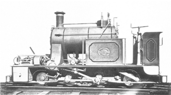
This is one of the six Fox, Walker ‘Handyside’ Locomotives 399 to 404 of 1878. The works photo has been doctored so that the works-plate reads ‘Peckett.’


The story so far … In France the young Péchot, burning to avoid any repeat of his country’s humiliation in the Franco-Prussian War, had developed a portable 60 cm gauge railway which could bring French guns and, more importantly, large quantities of ammunition within range of German forts. In 1882, after some years of theoretical work and experimentation at the Decauville factory, Péchot sent a description in a bold Memorandum to the French Minister of Defence/Ministre de la Guerre.
Unfortunately for Péchot, there was a rival system which had been proposed by the Génie/Military Engineers…
In Britain, there was also interest in railways for military support. Since the early 1870s, an 18” (45cm) gauge railway had existed at the Chatham Dockyards, Kent. A gauge so narrow was chosen because it could tolerate tight bends. It was therefore cheap to engineer - and convenient for running inside buildings. In the early 1880s, the young Péchot had considered the metric equivalent but after careful theorising and experimentation decided that 60cm gauge could offer almost the same advantages with fewer drawbacks.
Courtesy of the Industrial Railway Society
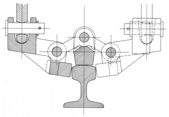
This picture of the  Handyside gripper originally appeared in 'Iron' magazine 1874.
Mr Henry Handyside, formerly Assistant Engineer to the Governor of Nelson Province New Zealand,  made a most interesting attempt to fit 18” gauge to the demands and problems of railway gradients. He invented a steep gradient gripping strut capable of holding a locomotive and a train. The theory was that the grippers would keep the locomotive in pace while it acted as a stationary engine with winch.  Manageable sections wof the train could be pulled up (or down). Supporting subscribers of the Handyside Steep Gradient Company included E. Fox, F.W. Fox and E. Walker. Fox, Walker & Co of the Atlas Works near Bristol funded much of the development of his system.
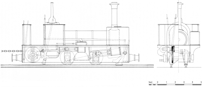
Drawings appeared in Iron Magazine 17th October 1874 showing a proposed conversion of a Manning Wardle to take the winding engine to be used in conjunction with the Handyside Gripper.
Courtesy of the Industrial Railway Society/Roger West


The proposed conversion of Manning Wardle no 448 0-4-0 ‘Burgoyne.' The drawings by Roger West are a clarified version of the originals which appeared in the magazine. The winding engine is of the ‘non-reversing, no-lead’ type typical of the period.


Just as with their Continental equivalents, the Royal Engineers took some convincing. Equally, as with Péchot and his commercial backer Paul Decauville, Handyside had support from Fox, Walker and Co. The Handyside System was tested using standard gauge in 1875. This finally persuaded the Royal Engineers to have a look.  On 12th September 1876, an 0-6-0 ST locomotive equipped with the gripping strut was to be put through its paces in front of Major Percy Smith RE and Captain Sale RE at a 1:14 gradient section of the Hopton Incline, Crompton and High Peak Line, Derbyshire. The Royal Engineers reported that the system had problems but potential.
In November that year, the RE proposed to use the Handyside system for 18” gauge. They wanted to link Chatham with Fort Borstall, at the time under construction, and ordered six special locomotives. David Smithers remarks that the design was ‘influenced by the double Fairlie principle ( in his 18” Gauge Steam Railways OPC 1993 p109.)’ In 1878, the Atlas Works of Fox, Walker & Co duly supplied six locomotive (Works Nos. 399 to 404) which were fitted with the Handyside Steep Gradient Apparatus.


By May 1879, the RE were ready to report on the performance of the new system. The trial railway in Chatham consisted of three bridges, four turnouts, several tight bends and some gradients, up to 1 in 11.  The railway was ‘as standard’ for a ‘trench railway’ according to the Minute of the RE Committee 2nd May 1879. The locomotive was able to pull 10 tons (Imperial) up a I in 10 incline. A number of problems emerged, the chief one being that trains could not cope with poorly laid track.
In 1881, and again in 1883, one locomotive at least was partly overhauled to try to meet the challenges. A report from Major Hogg fell on the desks of the senior RE Committee and appeared in the RE Journal for September 1885. It was unfavourable. In Hogg’s opinion, 18” gauge locomotive-worked railways were not suitable for siege train purposes on the grounds of cost and safety.
It should be noted that in the late 1870s, the British Army were more inclined to put money and effort into developing military railways. They feared a new war in Russia. By 1881, the threat had receded and the impetus was lost. The Committee therefore decided to shelve the siege train project; a metre gauge system would answer their purposes better. No more was done. In due course, the official siege train gauge was changed to 2’6” though by 1914, this consisted of a mere 2 ½ miles of track.
I must declare an interest here. In 1895, ten years after these events, my great grand-father, then Major Louis Jackson, was Chief Instructor of Fortifications and Engineering at Chatham.
Louis Charles Jackson later Sir General Louis Charles Jackson 1856 to 1946
In the period 1882 to 1885, events in France followed a similar pattern to Britain.
The Péchot Memorandum of 1882 was accompanied by some illustrations. 

Illustration from the Péchot Memorandum of 1882 Courtesy of Raymond PÉCHOT
Here the locomotive pulling a large gun is being winched up a gradient. Though Péchot gives many details for other parts of his system, he does not, apart from a brief reference in Appendix 8 of his Memorandum, expand much on winch haulage systems.  Why not? Everything else in the Memorandum is meticulously explained. It is hard to believe that he was not following the RE and Atlas works trials in England.
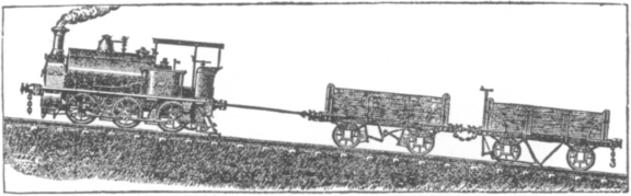
From an advertisement 1875 Courtesy of the Industrial Railway Society

The advertisement dated 1875 for the Handyside Steep Gradient Company shows gripping struts on the second wheel of a Fox, Walker Atlas Works 0-6-0. A short test-track was constructed at the Atlas works, Bristol – this engraving was based on fact! A hauling drum for pulling loco and train up the gradient was also used at the trials. The two systems bear direct comparison.


An enthusiastic officer, in the French case Péchot, with the backing of a private company, in this case Decauville, tried to solve the Army’s transport problem in covering the last ten miles between an existing railway station and a fort. Trials were performed from July 1883 to June 1885, basically at the expense of Decauville and existing civilian railways.
The French Génie/Engineers discovered the interesting fact that an pre-existing metre gauge railway was the most cost-effective way to move supplies. Péchot was reprimanded for suggesting otherwise. Just as in Britain, the senior engineers reported that the way to move supplies in war-time was to requisition metre gauge stock and left it at that. In my book Colonel Péchot: Tracks To The Trenches, I expand on this decision with many exclamation marks!
Courtesy Tim Dowling: Decauville locomotive similar to the one in the Péchot drawing. It is pictured on the Phu Lang Thuong-Lang Son, Annam/modern Vietnam. A 60cm gauge railway was built in 1889. This was replaced, starting in 1896 with a metre gauge railway
In France, the Péchot system was mothballed then revived. This was partly because of the remarkable character of Prosper Péchot, partly due to politics. Unlike for the British Isles, the chief enemy of France was Germany, just over the frontier. To keep her away a network of fortifications stretched along eastern France. In 1886, these forts were threatened with a deadly new threat, artillery using new high explosives. It became essential to protect them. Each fort was therefore surrounded in turn with other forts! A handy, budget line of communication was needed and Péchot’s ideas were revisited. Perhaps if the free Press had not become involved or if the Minister of Defence had not been a comparative outsider, immune to the in-fighting between the Génie and Artillerie, the problem would have been quietly buried.
As it was, in 1888, the système Péchot was declared the official railway linking all the frontier forts. By the early 1890s, a 60cm network of nearly 700 km/450 miles was in construction, to be operated by 56 Péchot-Bourdon locomotives. These owe something to 5 tonne Decauville locomotive design but were, in Péchot’s own words ‘in the spirit of Fairlie’.
It is no coincidence, I have argued in the Péchot biography, that the Germans suddenly switched to 60cm gauge for military applications and had over 1000 km of their Feldbahn system available in 1914.

Monday, 5 October 2015

Camouflage on a war department railway

When the First World War began, the British were ahead of the French in camouflage - through sad experience. Khaki was the standard colour of their uniforms. Khaki - a Hindi word meaning earth coloured - was first used in military uniforms in British India in the mid-nineteenth century. The Meerut Guides were known as the Khaki Risala (khaki squadron). It was not generally introduced to the British Army until the Boer War 1899-1902; their bright uniforms presented the Boer snipers with excellent targets. By 1914, at the outbreak of war,even the kilts of the Scottish regiments and the uniforms of mounted officers were khaki.
It was not a perfect system, because hey! the Flanders mud and vegetable detritus was not khaki. Camouflage had to become more subtle.
The French learned from sad experience that their beautiful patriotic red-white-and-blue uniforms did not work in the field and went over to horizon blue for uniform. This was also the colour of the basic paintwork of the locomotives and rolling stock of their 60cm gauge field railways, originally designed by Prosper Péchot.

This painting by François Flameng shows a French trench at Mont Renaud in eastern France 1918. We can see that French horizon blue is not ideal, but a good overall camouflage colour. From Illustration magazine
This desperately sad picture of a trench shows that this greyish blue works. With the inevitable mud on their faces, the effect was complete - as long as they stayed still.
In a form of parallel evolution, locomotives used on the WDLR, the British 60cm gauge railways, were painted a darker grey. 
The art of camouflage had to go a little further. In 1909, the artist and naturalist Abbott Handerson Thayer had put forward the idea of  Disruptive Camouflage. He wondered why zebras have stripes and leopards spots. This disruptive colouring must have been successful, he assumed, by breaking up the outline of the person or object. As the first world war dragged on, the military began to use such ideas, though on objects rather than army uniform. Blotches near the edge of a vehicle would help to disguise straight lines.
16mm model of a WD class H (tanker) wagon built by Jim Hawkesworth using Wrightscale WD bogies.

This fine model of a WDLR water tanker Class H on Wrightscale WD bogies demonstrates the theory in action. Placed against a white background, it shows up like a jester in a carpark. If the model were running through dappled shade, it would be a different matter! Blotches break up the straight outline and bold vertical patches disrupt the horizontal flow of the eye. It was designed and painted by Jim Hawkesworth.
You may be wondering how he decided on the colour scheme. We know there were a number of artists working especially in Britain and the USA to develop ideas about camouflage.They came up with dazzle (in the USA razzle-dazzle). Not only should spots and stripes disrupt the outline but they would actually make it hard to judge speed and distance.
Entitled 'chars d'assaut' (assault tanks) July 18 - painting by François Flameng. From Illustration magazine.

We see the sharing of Allied ideas on a French St Chamond tank of 1918. This contemporary illustration by Flameng is particuarly useful by being in colour. We see how the monster's outline is broken up, all the better for it to sneak up on the enemy trenches and evade their guns. The colours - green, khaki, red and brown - might seem rather bright, but applied in combination they tone in the landscape. They are applied in splodges, all the better to break up the straight edges of the vehicle.
Other forms of camouflage were used. The screen is effective, especially to conceal movement in daylight. Such screens were used to conceal railway loading bays, at vulnerable points where there was no ground cover or to screen activity from the air. The observation balloon was much used from the late 19th century but but observer aeroplanes were soon in use by both sides. The Germans quite effectively used aerial troops and Zeppelins (manned balloons) for observation and bombing.

Entitled 'Canon de 138,6 de la marine' this picture by Henry Cheffer was made in June 1918. Now at full strength, the AEF had just engaged with the German Army at Bois de Belleau. The French called it la rupture/breakthrough. Illustration
Here a 380mm gun is screened from the air. The coloured mesh helps to break up outlines, but also enables vegetation to be laid over the gun and crew, hiding them without hampering their work.